
xTool X1: everything we know
A live, source-linked evidence desk for the follow-up video: launch footage, timestamped claims, close-up machine images, FCC scale evidence, pricing benchmarks, patent research, and the questions xTool has not answered.
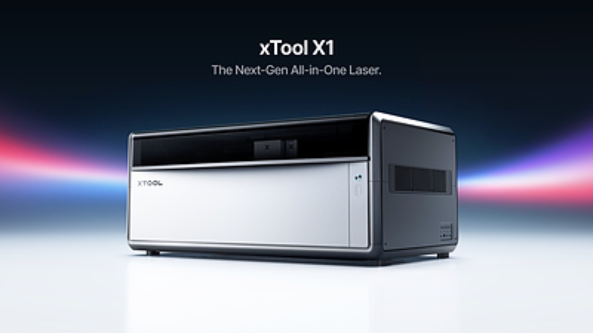
The short version
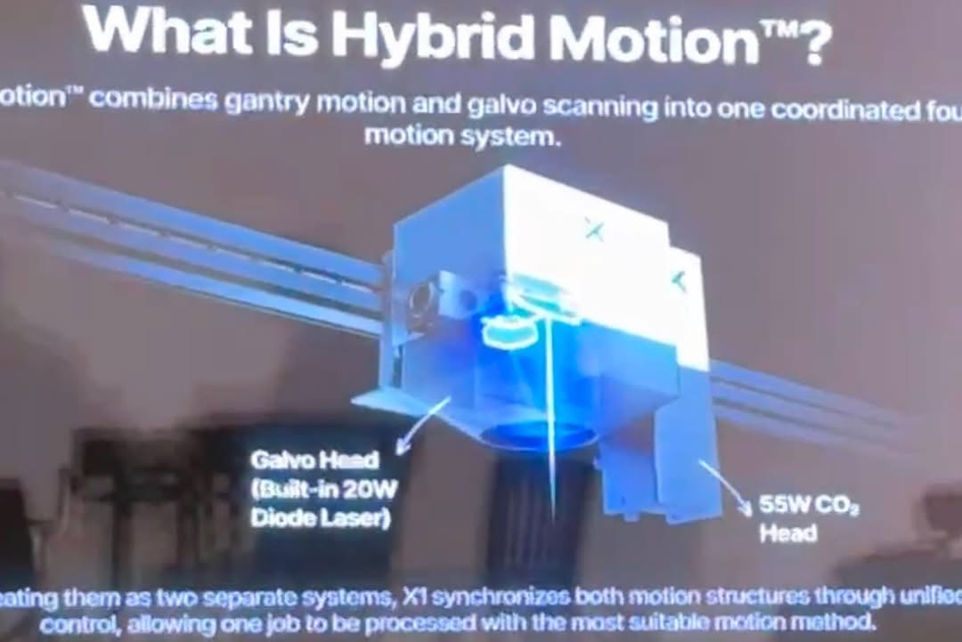
X1 is best understood as two laser architectures sharing one enclosure and motion platform: a flying galvo for the permanent 20 W diode plus one selected rear-fed UV, fiber, or MOPA module, and a separate moving 55 W glass CO₂ head. Our strongest pricing model is $5,999 MSRP / $4,999–$5,499 at launch for the base machine, $8,999–$9,499 for an all-source bundle, and up to roughly $12,499 for every source plus production accessories and industrial air cleaning. None of those prices are official.
Known at a glance
Read the label on every fact. “Official” means xTool published it; “reported” means an attendee said or showed it; “FCC” comes from the certification exhibit; “estimate” is our reconstruction.
Open the videos live
Every evidence button opens YouTube at the useful moment. My Simple Builds has the best complete presentation; Laser Engraving 911 has the best closeups and reported dimensions.
My Simple Builds · “In the Room Where it Happened”
Complete landscape recording of the X1 presentation, published August 28, 2026.
Laser Engraving 911 · “The Biggest Laser Announcement Yet?”
Michael’s hands-on event footage, published August 28, 2026.
xTool · Next Level Maker Conference livestream
Authoritative event provenance, though the vertical stage footage is less useful than the attendee recording.
Diode Designs · “xTool X1 Debut”
A concise X1-only stage sequence with the engineering slides and source list.
Abby’s Attic Creations · conference reaction
Useful unveiling and floor perspective, including a clearer sense of the machine’s physical scale.
xTool · X1 technology teasers
Short official renders of the motion head, material coverage, wavelength paths, and closed machine.
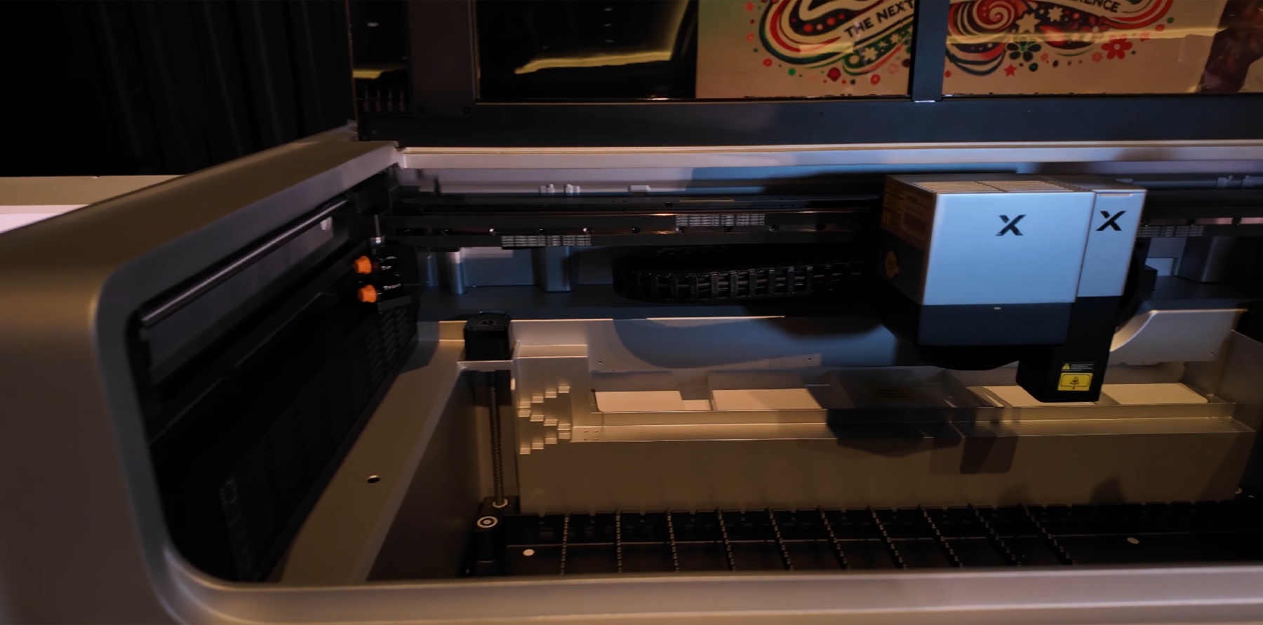
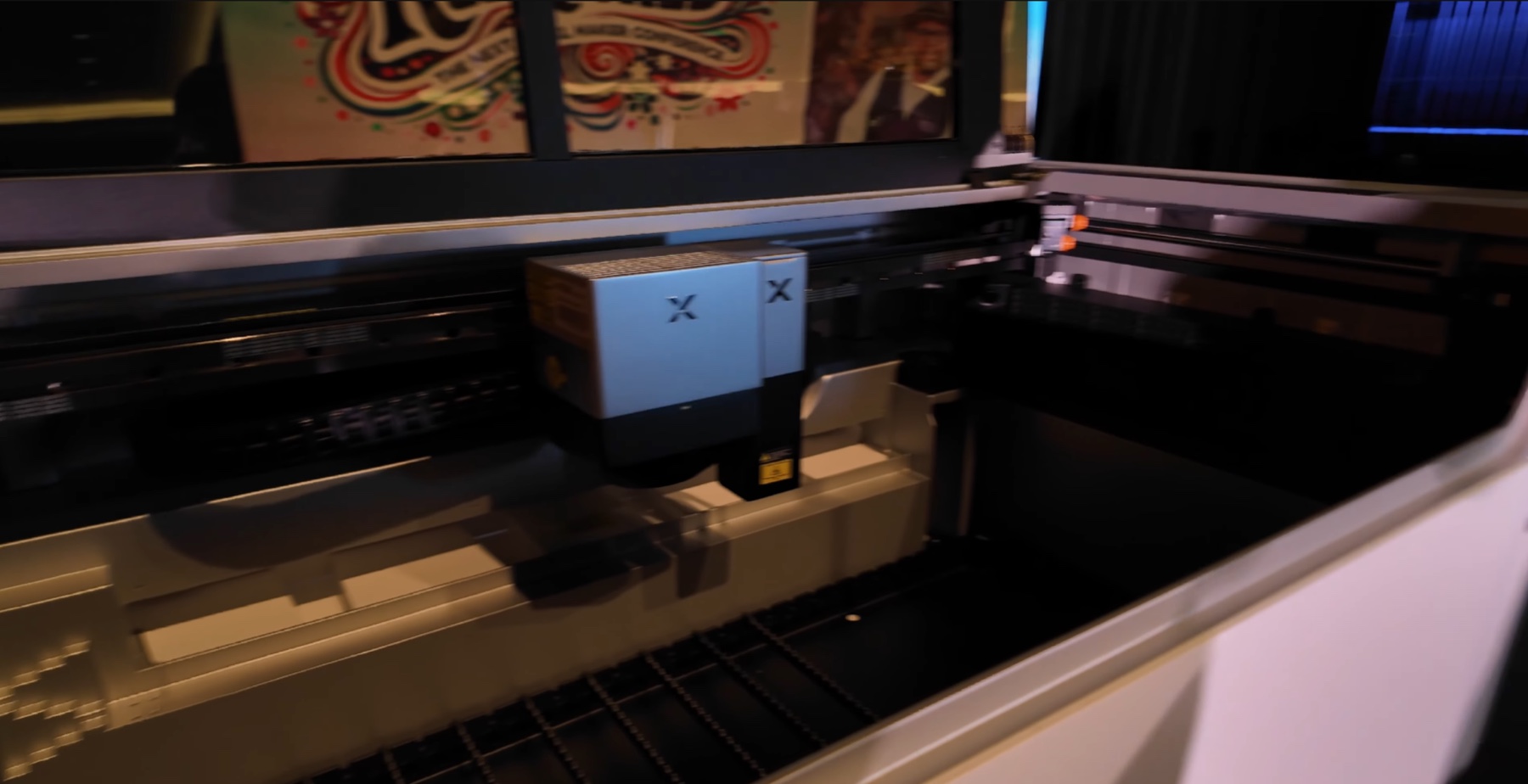
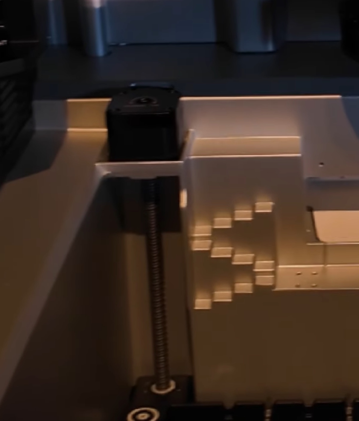
Machine closeups
These frames are prepared for on-screen reference. Open the timestamp in each caption to show the original source and context.
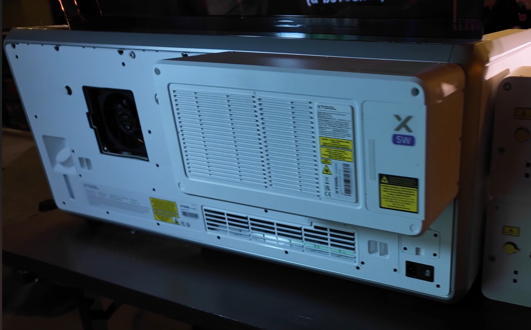
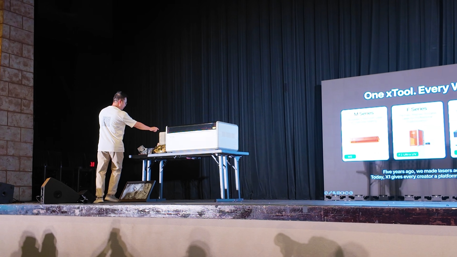
Size, Z height and pass-through
The work area comes from an attendee report. Exterior measurements are our ruler-based estimate from the FCC exhibit, not final xTool dimensions.
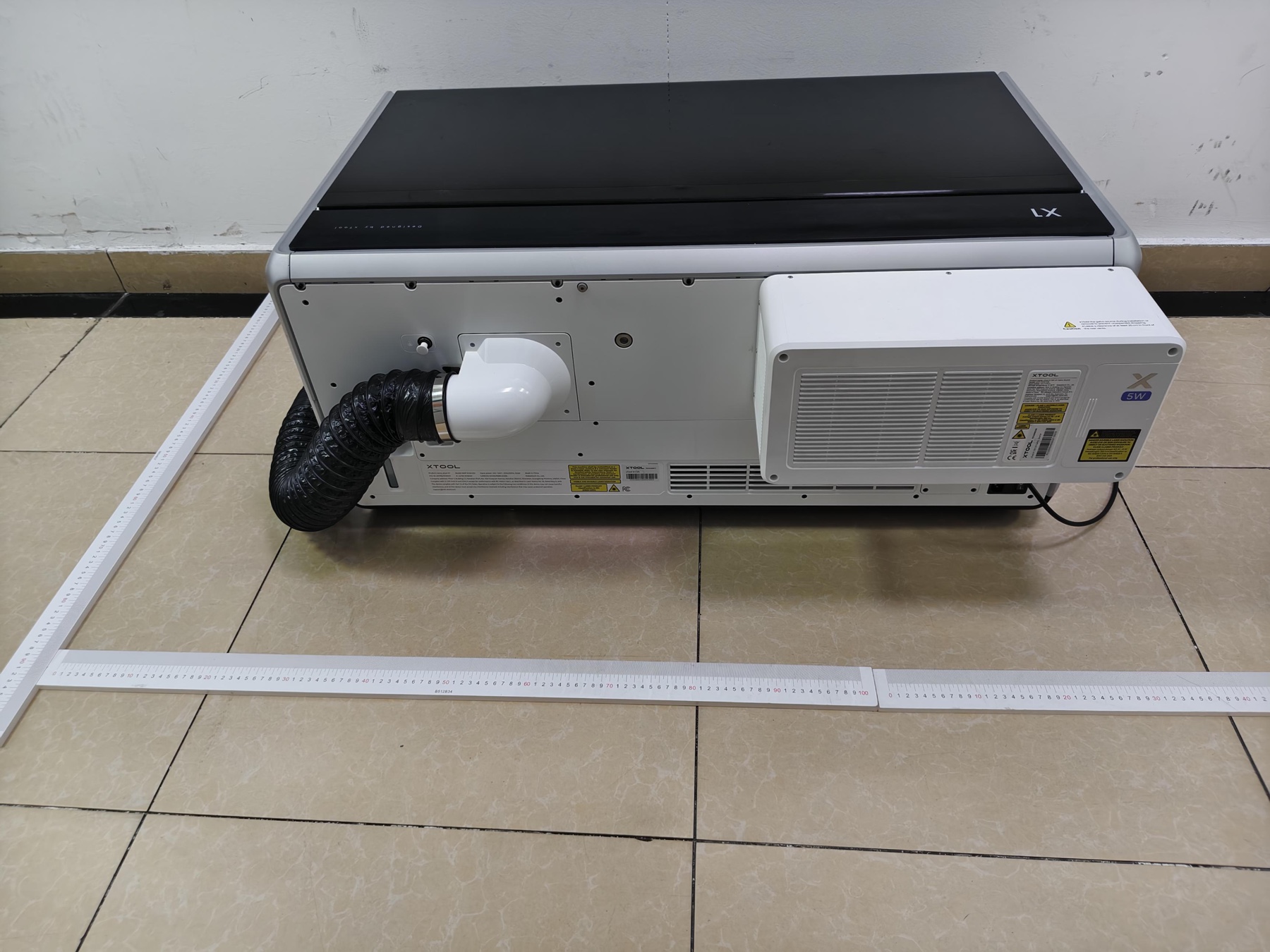
- Work area24 × 12 in (about 610 × 305 mm), reported by Laser Engraving 911.
- ExteriorRoughly 1,000 × 750 × 380 mm for the closed main chassis. The installed rear backpack adds depth.
- ScaleP2S/P3 family footprint class, but deeper when a source backpack is installed.
- Z axisMotorized bed lift is visible and was demonstrated. The likely reference is P3's AutoLift platform, which officially supports up to 220 mm in manual mode and 180 mm in automatic mode. A similar X1 workbed range is plausible, but not confirmed.
- Pass-throughThe FCC label explicitly names a conveyor feeder. Installing it changes the product from Class 1 to Class 4, confirming an open-feed mode.
- UnknownOpening dimensions, conveyor width, supported material length, accessory price and whether a slatted conveyor is included.
Configuration-level pricing forecast
Live US Shopify variants and Machines for Makers price history checked August 28, 2026. Every X1 number is a forecast; every comparator links to the exact official product.
Strongest prediction: $5,999 list, $4,999–$5,499 at launch
The base X1 should sit above the mature $2,999 P2S because it adds a permanent 20 W diode, flying-galvo motion, modular source routing and likely P3-class automation. It should usually remain below the $6,999 P3 because its CO₂ source and work area are smaller. xTool could list X1 at $5,999 while using a $4,999–$5,499 launch price, then move toward $4,499–$4,999 during mature sales.
Likely X1 source prices
The center estimate values the proprietary backpack, power supply, cooling and calibration—not merely the commodity laser emitter.
| X1 component | Low | Center estimate | High | Reasoning |
|---|---|---|---|---|
| Base: 55 W CO₂ + permanent 20 W diode | $4,499 | $4,999 launch $5,999 list | $6,499 | P2S sets the floor; P3 sets the ceiling. New motion, galvo optics and automation create the premium. |
| 30 W fiber backpack | $999 | $1,499 | $1,999 | P3 charges $749 for only 5 W IR; this is a much higher-power source but avoids duplicating X1's enclosure and scan head. |
| 60 W MOPA backpack | $1,499 | $1,999 | $2,499 | F2 Ultra MOPA-only is $4,299 as a complete system. Its premium over F1 Ultra is $1,300, but that comparison also changes cameras, motion and power. |
| 5 W UV backpack | $1,499 | $1,999 | $2,499 | xTool prices the complete 5 W UV and 60 W MOPA F2 Ultra systems identically at $4,299, supporting equal module positioning. |
| Dedicated conveyor | $449 | $499–$599 | $699 | Current conveyors are $459 for P2S, $499 for F-series and $599 for P3. |
| RA3 rotary, if compatible | $299 | $349 | $399 | RA3 for P3/F Series is currently $349. |
Every likely source configuration
Point estimates use a $4,999 effective base, $1,499 fiber and $1,999 each for MOPA and UV. “All sources” means owning all three backpacks; the evidence still suggests only one optional backpack mounts at a time.
| Ownership configuration | À la carte math | Likely xTool package | Positioning |
|---|---|---|---|
| Base X1 | $4,999 | $4,999–$5,499 launch | CO₂ cutting plus permanent diode engraving. |
| Base + 30 W fiber | $6,498 | $5,999–$6,299 | Likely entry metal-marking configuration. |
| Base + 60 W MOPA | $6,998 | $6,499–$6,799 | Most compelling metal-production package; lands near P3. |
| Base + 5 W UV | $6,998 | $6,499–$6,799 | Glass, plastics and low-heat premium package. |
| Base + fiber + MOPA | $8,497 | $7,499–$7,999 | Some wavelength overlap makes this a less obvious promoted bundle. |
| Base + fiber + UV | $8,497 | $7,499–$7,999 | Broad material coverage without the highest-power metal source. |
| Base + MOPA + UV | $8,997 | $7,999–$8,499 | Likely high-value professional combination. |
| All three backpacks | $10,496 | $8,999–$9,499 | The obvious “all lasers” launch bundle; approximately 10–14% below point-estimate à la carte pricing. |
| All sources + conveyor + RA3 + AP2 | About $12,343 | $10,699–$11,199 | Complete desktop studio if the $999 AP2 can meet X1 airflow. |
| All sources + conveyor + RA3 + AP2 Max | About $13,843 | $11,999–$12,499 | Maximum configuration if X1 requires the $2,499 industrial purifier used with P3. |
What xTool’s live configurations tell us
These are nominal variant prices before temporary cart-wide coupons. They isolate several unusually useful component and bundle deltas.
| Official configuration | Live price | Exact delta | Signal for X1 |
|---|---|---|---|
| P2S standalone / versatile / all-in-one | $2,999 / $4,169 / $5,069 | +$1,170 / +$2,070 | Same 55 W CO₂ and nearly the same reported work area. Mature price is 33% below its $4,499 compare-at price. |
| P3 standalone / versatile / all-in-one | $6,999 / $8,209 / $10,459 | +$1,210 / +$3,460 | 80 W, larger bed and likely X1 automation family. Versatile adds the 5 W IR module, conveyor and RA3; all-in-one adds AP2 Max. |
| P3 5 W IR module | $749 | Standalone module | Direct proof that xTool charges a substantial premium for an integrated, calibrated low-power source module. |
| F2 Ultra MOPA-only / MOPA + 40 W diode | $4,299 / $5,299 | +$1,000 | Best isolated value for adding a 40 W diode to an otherwise comparable galvo platform. |
| F2 Ultra UV / MOPA-only | $4,299 / $4,299 | $0 difference | xTool positions complete 5 W UV and 60 W MOPA machines at the same price. |
| S1 20 W / 40 W | $1,299 / $1,699 basic | +$400 | Same-package diode power premium is $400–$490; standalone module difference is $586. |
| F-series conveyor | $499 standalone | $450 in machine bundles | About a 10% accessory discount. |
| SafetyPro AP2 / AP2 Max | $999 / $2,499 | $1,500 gap | Airflow requirement can swing the complete X1 studio price dramatically. |
How xTool discounts bundles over time
Data caveat: xTool changes campaign discounts independently of nominal Shopify variant prices. Historical F2 Ultra records also changed which default variant the page selected, so exact live variant IDs—not unlabeled tracker rows—drive the source-module comparison above.
What X1 is, what it is not, and who should buy it
The cleanest way to understand X1 is as a consolidation machine: P2S-class CO₂ cutting plus a large-format flying galvo, with optional professional engraving wavelengths.
The thesis: engraving-first, but still a real CO₂ cutter
X1's 55 W glass CO₂ source should cut in roughly the same class as P2S. What it is not is an 80 W, cutting-first P3 replacement—or a maximum-throughput fixed galvo. Its reason to exist is engraving across a much larger field, changing laser families without changing machines, and carrying P3-like cameras, bed motion and workflow automation into a smaller platform.
The 6,000 mm/s tradeoff
Maximum scan speed is only one part of real throughput, but it exposes xTool's positioning: X1 favors field size and coordinated gantry movement over the fastest possible fixed-galvo cycle time.
| Machine | Official maximum | Working area | What the comparison means |
|---|---|---|---|
| X1 | 6,000 mm/s | Reported 24 × 12 in | Same headline speed as F2, but with a dramatically larger field created by moving the galvo on a gantry. |
| F2 | 6,000 mm/s | 115 × 115 mm | Portable 15 W diode + 5 W IR; this is X1's closest speed match, not its closest power match. |
| F1 Ultra | 10,000 mm/s | 220 × 220 mm | About 67% higher nominal scan speed, plus a compact form that is easier to fixture and move. |
| F2 Ultra | 15,000 mm/s | 220 × 220 mm | 2.5× X1's maximum: the better pure production engraver when its smaller field can hold the job. |
Do not turn those ratios directly into job-time claims. Acceleration, hatch spacing, source power, material settings, gantry repositioning and how xTool divides a large path between the stage and mirrors will determine actual throughput.
X1 versus buying two machines
Current official standalone prices make the choice surprisingly close. The base X1 does not include fiber; its fair F1 Ultra comparison begins with the 30 W fiber backpack installed.
| Choice | Current / forecast price | You gain | You give up |
|---|---|---|---|
| X1 base 55 W CO₂ + 20 W diode | $4,999–$5,499 forecast | One workflow; very large diode-galvo field; likely P3-family camera, autofocus and lifting-bed automation. | No fiber, MOPA or UV without another purchase; lower scan-speed ceiling than either Ultra. |
| P2S + F2 | $4,498 today | Lowest-cost two-station option; portability; two jobs can run independently. | Only 5 W IR and 15 W diode in a 115 × 115 mm galvo field. |
| X1 + 30 W fiber | $5,999–$6,299 forecast | 30 W fiber and 20 W diode over the reported 24 × 12 inch area, plus integrated CO₂. | One shared production platform; 6,000 mm/s announced ceiling; unproven swap and calibration time. |
| P2S + F1 Ultra | $5,998 today | Two simultaneous machines; 10,000 mm/s galvo; compact 20 W fiber station with familiar jig workflow. | Smaller 220 × 220 mm galvo field, duplicated diode hardware and two software/device workflows. |
| X1 + 60 W MOPA | $6,499–$6,799 forecast | Large-field MOPA, diode and CO₂ in one calibrated coordinate system. | Less nominal galvo speed and less independent capacity. |
| P2S + F2 Ultra MOPA-only | $7,298 today | 15,000 mm/s MOPA station and concurrent CO₂ production. | Higher price, two footprints and only a 220 × 220 mm native galvo field. |
| X1 + 5 W UV | $6,499–$6,799 forecast | UV work over a much larger potential field, plus diode and CO₂ material coverage. | Large UV jobs may still be power-limited; the real stitched-field speed and quality are unknown. |
| P2S + F2 Ultra UV | $7,298 today | 15,000 mm/s UV station, independent CO₂ cutting and less risk from a first-generation hybrid platform. | More floor/bench space and a much smaller UV field. |
What we can answer now
The patent families help explain the architecture, but a patent embodiment is not a shipping specification.
Is the metal base an RF CO₂ source?
Almost certainly no. The event identifies a 55 W glass tube, and the base feature aligns with the vertical bed mechanism. Its ribs, steps and fasteners read as a cast structural platform.
Does it need an external chiller?
Apparently no. Rear vents and the absence of an external unit point to a closed internal water loop, similar in concept to P2S. Exact coolant and service procedure remain unknown.
How does the beam path work?
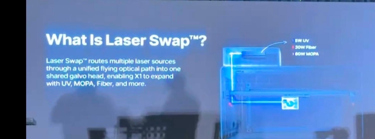
The rear UV/fiber/MOPA source and built-in diode feed a shared flying galvo. The CO₂ tube follows a separate free-space mirror path to the smaller adjacent head.
Can all optional sources stay installed?
Probably not. The prototype shows one rear expansion position and xTool physically swaps backpacks. Auto-identification/calibration is plausible; the connector and hot-swap procedure are not public.
Will it inherit the P3 sensor and AutoLift setup?
Probably much of it. P3's ACS combines a 16 MP panoramic camera, close-view detail camera, LiDAR autofocus, automatic positioning and an AutoLift bed; xTool also markets a four-camera total when safety monitoring is counted. X1 already shows plural cameras and a similar built-in lifting bed, making this the strongest family-pattern prediction. The X1 camera count, LiDAR, fire hardware and exact 220/180 mm P3 height limits are still unconfirmed.
Is X1 just a parts-bin machine?
The sources borrow heavily; the integration does not. Its 55 W CO₂, 20 W diode, 60 W MOPA and 5 W UV classes map neatly onto P2S, F1 Ultra and F2 Ultra hardware families. The moving flying-galvo head, large-field multi-source calibration, stiff cast datum structure and coordinated stage-plus-mirror control are the real X1 engineering.
Does xTool have a removable galvo-head concept?
Yes, but it is not proven for X1. WO2026017037A1 explicitly describes one diode-galvo head that can move between a large X/Y/Z gantry and a compact stand, including a shared fixing plate and a switch that identifies the installed frame. Neither the patent nor the launch footage says the revealed X1 multi-source head uses that mount or can leave its enclosure.
Will it support LightBurn?
Very unlikely at launch. xTool says products launched after August 2025, starting with P3, are Studio-only. There is no X1-specific compatibility page yet.
What does October mean?
The presenter corrected himself to say they aim to launch in October while still improving the machine. That supports an October announcement or presale target, not a promised ship date.
What still matters most?
Final dimensions and weight, usable Z height, camera/focus stack, conveyor opening, exhaust airflow, coolant service, swap calibration, warranty, tube life, price, bundles and delivery date.
Technical deep dive
The rest of this page reconstructs the optical architecture and preserves the full patent translations behind the analysis.
How the X1’s light paths appear to work
The launch slides show two different optical architectures. Treating them as one universal path is the mistake that makes the machine confusing.
Reconstructed X1 architecture
Solid descriptions come from the event slides and patent families. The exact switch, lens stack and rear-bay concurrency are not public.
Important: “Laser Swap” and the single physical UV pack support a swappable rear-source interface. The public evidence does not establish two rear expansion packs installed together.
The CO₂ head rides to the right of the galvo on the gantry. Its beam travels through free space and moving mirrors, not through the non-CO₂ galvo path.
That equation is an industry-derived reconstruction consistent with xTool’s “four-axis,” path-planning and motion-compensation language—not a disclosed X1 control algorithm.
So can UV and fiber be attached at the same time?
Not proven. The patents allow multiple emitters to feed one shared galvo, and the built-in diode can coexist with a rear-fed source. But the event hardware and “Laser Swap” language are equally consistent with one rear expansion source at a time. Until xTool publishes the rear-bay mechanical interface or manual, simultaneous UV plus fiber installation should be treated as a patent-backed possibility, not an X1 specification.
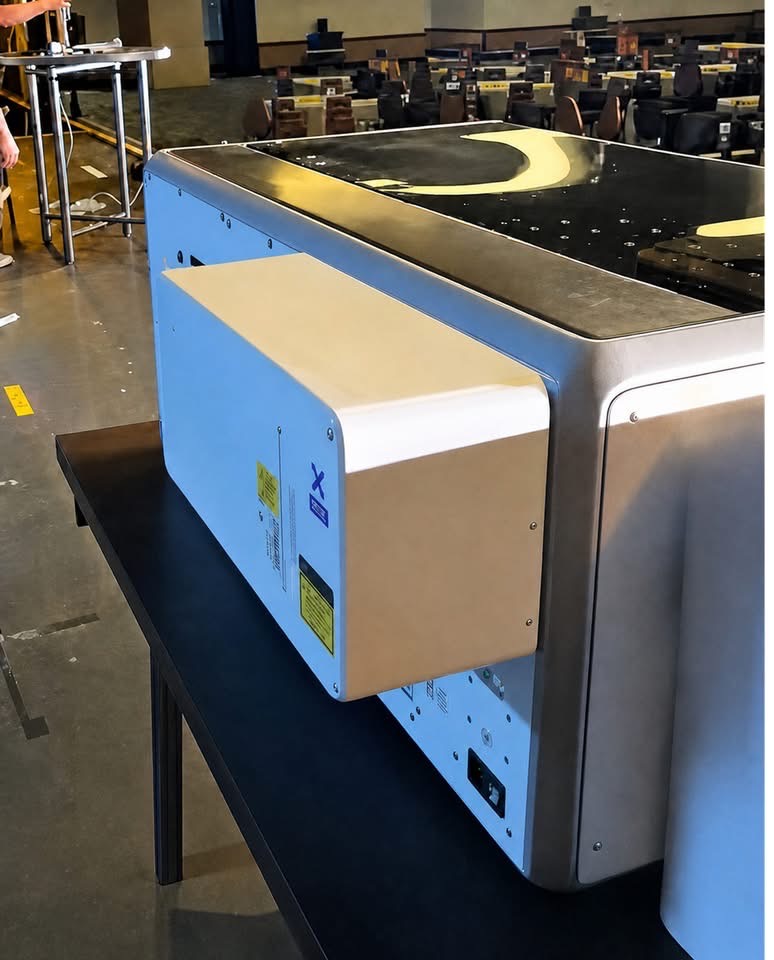
What xTool physically showed
The event photos are stronger evidence than product-category speculation. They establish the source powers, layout, and at least one working rear module.
The Makeblock patents that explain the system
No single public patent is labeled “xTool X1.” Together, however, these families describe the exact problems the event presentation claims to solve.
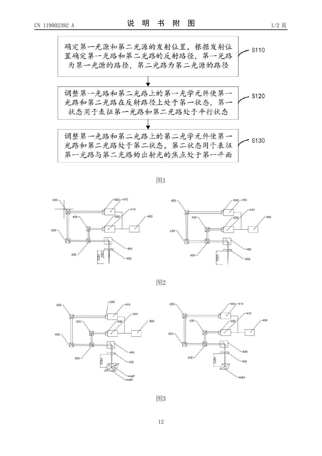
One calibrated field for different wavelengths
The family aligns multiple sources to a shared coordinate system, adjusts their beam divergence so focal planes coincide, and stores source-specific galvo parameters for rotation, scale, distortion and translation.
- Different wavelengths do not naturally land at the same focus or field coordinates.
- Calibration patterns are engraved with different sources and measured against one another.
- The correction prevents ghosting and blur when one job changes laser source.
Two emitters feeding one galvo
Two laser emitters pass through source-specific adjustment and reflectors, then a beam-combining mirror sends either path into one sealed two-mirror galvanometer assembly. The disclosure permits different types and power levels. Its Figure 8 mounts that processing head on a vertically adjustable support over a workbench, so this is one source of the stand-mounted galvo idea.
The actual interchangeable-head filing
This is the filing that directly supports the two-motion-platform idea. It describes one processing head containing a semiconductor laser, two motor-driven galvo mirrors and a focusing lens. The same fixing part can attach that head to either a large X/Y/Z motion frame or a compact support-and-worktable stand. The connection may use screws, snap fits or magnets, and a switch or sensor tells the controller which frame is installed.
Important limit: the drawings show a self-contained diode-galvo head, not the revealed X1's separate CO₂ path or rear-fed UV, fiber and MOPA modules. This is evidence that xTool patented a portable head shared across two frames. It is not evidence that the retail X1 head will undock.
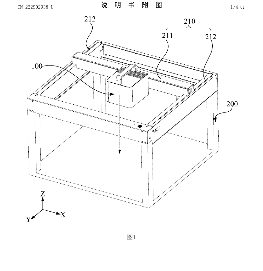
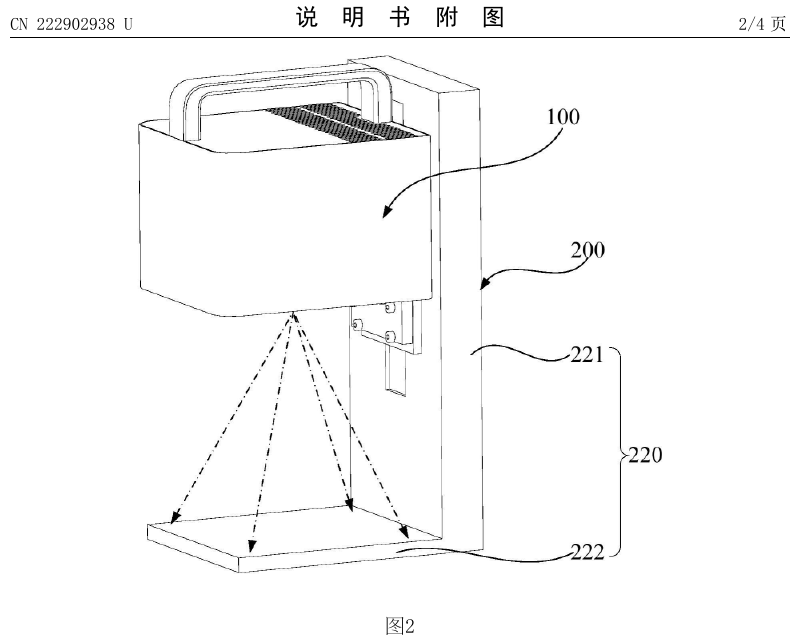
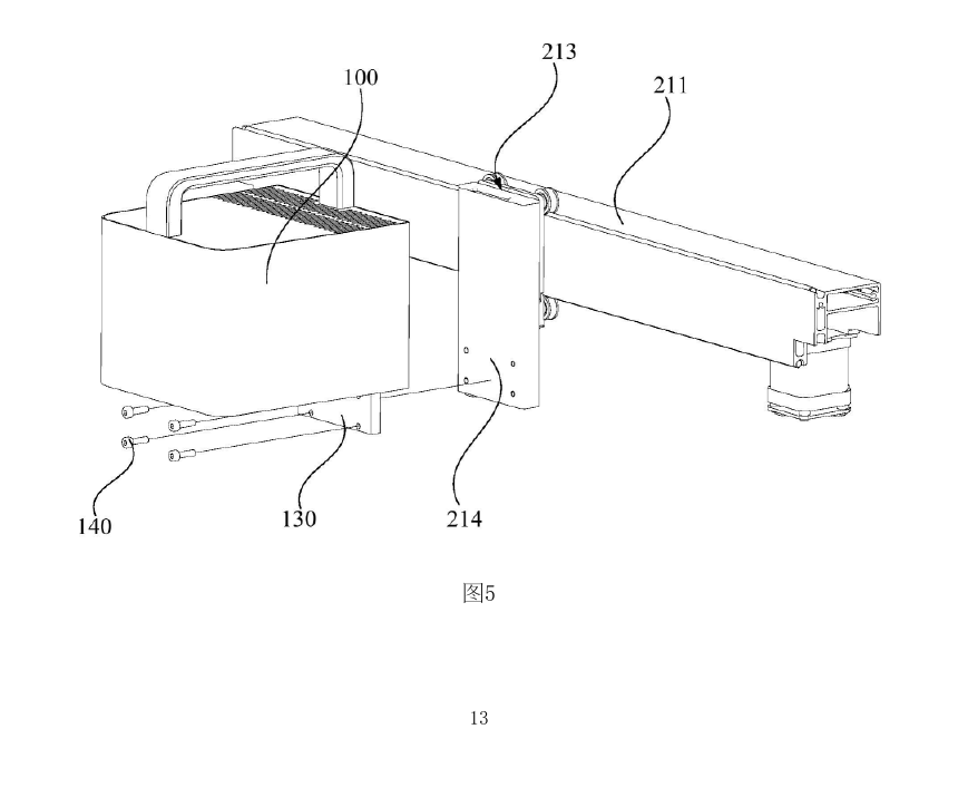
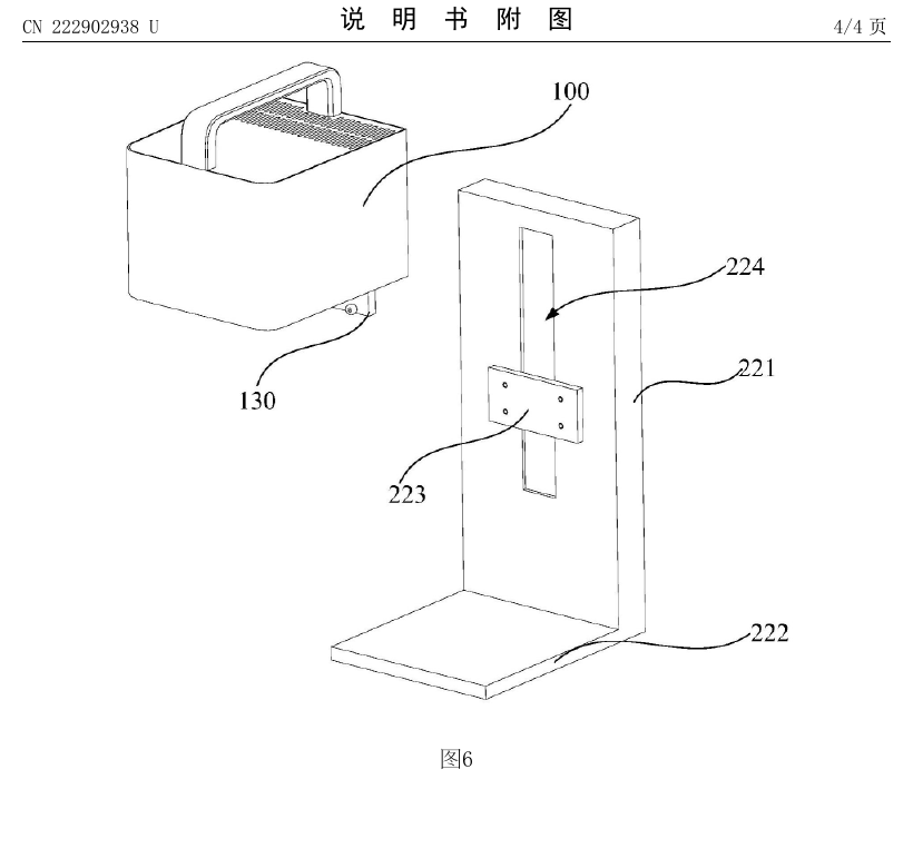
The F1 Ultra-style stand architecture, not interchangeable-head evidence
This is the familiar F1 Ultra-style stand architecture. A diode source remains in the processing head while a fiber source body sits on the vertical support and sends its beam through optical fiber to an output head. Both paths feed the processing head's mirror assembly, shared two-axis galvanometer and focusing lens. It explains xTool's compact dual-source packaging, but it does not say that this head transfers to an X1 gantry or any second chassis.
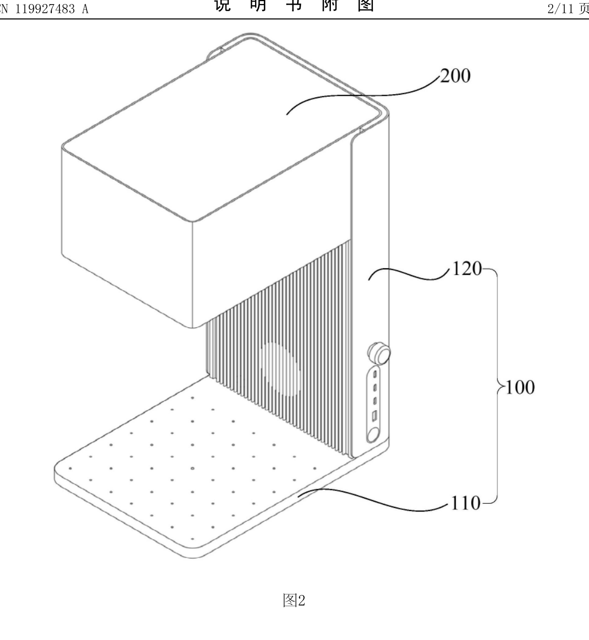
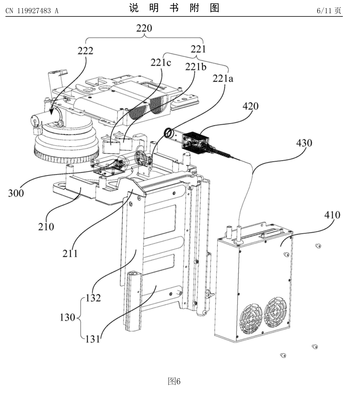
The X1-like body, and a false lead
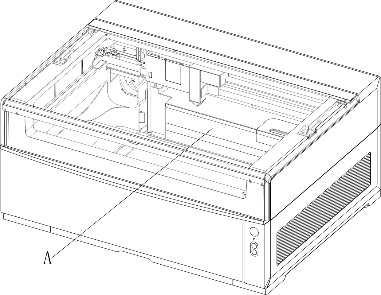
Correction: CN309785546S strongly identifies the X1-like enclosure, but CN309785544S should not be presented as its galvo head. That separate filing depicts a boxy gantry-style head with a narrow lower nozzle, not the broad lower housing and focusing optics visible on the revealed X1 galvo assembly. Similar timing and a shared inventor are not enough to connect the two designs.
What is actually new—and what is not
Flying a galvo on a mechanical stage is established industrial technology. Research papers described continuous scanner-stage subtraction by 2011; Aerotech and SCANLAB already sell look-ahead systems that divide a path between mechanical axes and galvo mirrors.
| Part of the story | Assessment | Why |
|---|---|---|
| Galvo mounted on a gantry | Established prior art | Documented industrial IFOV/on-the-fly architecture predates X1 by many years. |
| Four coordinated axes | Established prior art | Existing papers, controls and patents describe mechanical X/Y plus galvo X/Y interpolation. |
| Consumer enclosure with five laser families | Unusual desktop integration | X1 combines rear-fed 355/1064 nm modules, built-in diode and separate CO₂ inside one Class-1-style platform. |
| Automatic multi-wavelength registration | Credible xTool differentiator | Makeblock’s 2023-priority family directly addresses shared focus, field mapping and per-source distortion. |
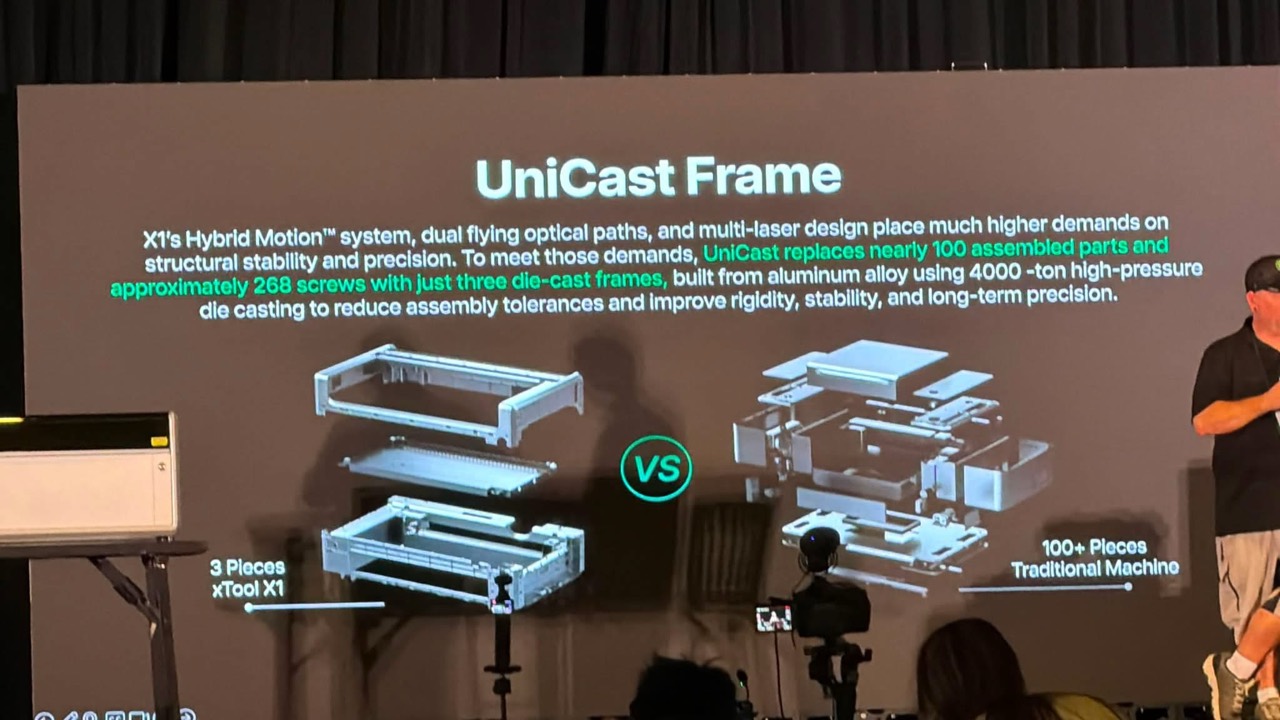
| Die-cast optical datum | Likely enabling hardware | Long-term registration across gantry, galvo, modules and CO₂ relay depends on structural repeatability. |
| One removable diode-galvo head across gantry and stand | Makeblock patent concept | WO2026017037A1 explicitly claims the shared mount and frame-detection switch, but no public X1 material adopts it. |
| Simultaneous UV and fiber rear modules | Not established | The patents allow multiple emitters, but public X1 hardware shows one rear module and uses “swap” language. |
The defensible claim is not that xTool invented the flying galvo. It is attempting to turn a difficult industrial control and calibration stack into a desktop platform where several laser families behave like one machine.
ACCELaser reached the desktop flying-galvo market first
ACCELaser’s HD1 Kickstarter ran in May–June 2025, more than a year before the X1 reveal. Its two January 2025 Chinese filings explicitly describe a slow XYZ gantry carrying a fast three-axis optical scanner, two remote optical-cable inputs, a beam combiner, and a motor-driven dynamic-focus carriage.
| Question | xTool X1 | ACCELaser HD1 |
|---|---|---|
| Flying galvo | Hybrid Motion revealed in 2026; exact control algorithm unpublished. | XYZ-carried 3D galvo patented and publicly crowdfunded in 2025. |
| Fast optical Z | Not proven in the event material. | Explicit motor/linkage moves the optical-focus carriage. |
| Source architecture | Built-in diode plus rear-fed UV, fiber or MOPA through shared galvo. | Two optical-cable inputs combine inside the moving head. |
| CO₂ system | Separate 55 W head and free-space relay path. | No comparable CO₂ architecture located. |
| Calibration disclosure | Strong patents for co-focus, field registration and source-specific galvo correction. | No comparably detailed public multi-wavelength calibration claim located. |
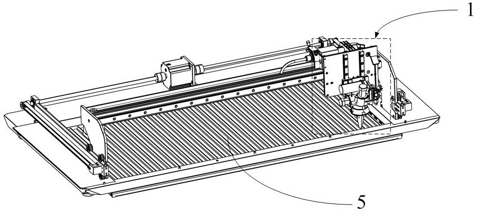
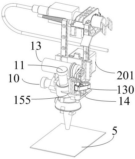
CN122322696A · Figures 1–9
- Complete machine, first perspective.
- Complete machine, second perspective.
- Left-side view.
- Front view.
- Galvo module perspective.
- Internal scan and zoom-focus structure.
- Sliding carriage.
- Coarse Z module.
- Dynamic-focus linkage.
CN223848324U · Figures 1–7
- Complete dynamic-focus module.
- Scanning and zoom arrangement.
- Sliding carriage.
- Coarse Z module.
- Dynamic-focus displacement unit.
- First housing perspective.
- Second housing perspective.
Complete English translations of the ACCELaser filings
These are technical English renderings of the public Chinese publications, included because they contain the clearest located patent explanation of the competing flying 3D-galvo mechanism. They are not certified legal translations.
CN122322696A · Laser processing apparatus
English abstract
The application provides a kind of laser processing equipment, comprising: laser processing galvanometer module, the laser processing galvanometer module is used to output laser to process workpiece;And motion frame, the motion frame includes X-axis movement module, Y-axis movement module and Z-axis movement module, the X-axis movement module, the Y-axis movement module and the Z-axis movement module are respectively configured to drive the laser processing galvanometer module relative to the workpiece movement on X-axis, Y-axis and Z-axis;Wherein, the laser processing galvanometer module includes first scanning device and second scanning device, the first scanning device and the second scanning device are used to change the position of the laser on the workpiece;And zoom device, the zoom device is used to adjust the focal length of the laser.
Complete translated claims (15)
- 1A laser processing apparatus characterized by comprising: include: A laser processing galvanometer module, wherein the laser processing galvanometer module is used to output laser light to process workpieces; and A motion frame, comprising an X-axis motion module, a Y-axis motion module, and a Z-axis motion module, wherein the X-axis motion module, the Y-axis motion module, and the Z-axis motion module are respectively configured to drive the laser processing galvanometer module to move relative to the workpiece along the X-axis, Y-axis, and Z-axis; The laser processing galvanometer module includes a first scanning device and a second scanning device, which are used to change the position of the laser on the workpiece; and a zoom device, which is used to adjust the focal length of the laser.
- 2The laser processing apparatus according to claim 1, characterized by, The X-axis motion module includes a first guide axis and an X-axis drive motor, the X-axis drive motor being configured to drive the laser processing galvanometer module to move relative to the workpiece along the first guide axis, and the Y-axis motion module includes a second guide axis and a Y-axis drive motor, the Y-axis drive motor being configured to drive the laser processing galvanometer module to move relative to the workpiece along the second guide axis.
- 3The laser processing apparatus according to claim 2, characterized by The first guide shaft is equipped with the Z-axis motion module, which includes a Z-axis drive motor and a galvanometer module guide structure. The galvanometer module guide structure is configured to move the laser processing galvanometer module on the Z-axis under the drive of the Z-axis drive motor.
- 4The laser processing apparatus according to claim 1, characterized by The first scanning device includes a first lens and a first motor, the first lens being configured to rotate under the control of the first motor; the second scanning device includes a second lens and a second motor, the second lens being configured to rotate under the control of the second motor; the zooming device includes a trolley unit and a galvanometer motor, the trolley unit being configured to move in the Z-axis direction under the control of the galvanometer motor.
- 5The laser processing equipment according to claim 4, characterized in that, The laser processing equipment further includes a beam combining device, which includes a first laser input end, a second laser input end, a first optical path reflector, and a second optical path beam combiner. The second optical path beam combiner is configured to combine the laser beams from the first laser input end and the second laser input end to obtain combined beam light.
- 6The laser processing equipment according to claim 5, characterized in that, The laser processing equipment also includes a second reflector, which is used to emit the combined beam onto the trolley unit.
- 7The laser processing equipment according to claim 5, characterized in that, The first laser input terminal and the second laser input terminal each include an optical cable, which is connected to the laser source.
- 8The laser processing equipment according to claim 5, characterized in that, The trolley unit includes a galvanometer and a galvanometer displacement unit. The galvanometer displacement unit includes a first rotating arm connected to the output end of the galvanometer motor and a second rotating arm pivotally connected to the first rotating arm.
- 9The laser processing equipment according to claim 8, characterized in that, The trolley unit also includes a connecting end pivotally connected to the second rotating arm, and a first guide unit.
- 10The laser processing equipment according to claim 9, characterized in that, The first guide unit is slidably connected to the second guide unit disposed on the laser processing galvanometer module. The trolley unit is configured to drive the first rotating arm and the second rotating arm to rotate by the rotation of the galvanometer motor, so that the trolley unit moves along the second guide unit in the Z-axis direction.
- 11The laser processing equipment according to claim 10, characterized in that, The first guide unit includes a guide hole, the second guide unit includes a guide post disposed on the housing, and / or the first guide unit includes a guide post, and the second guide unit includes a guide hole on the housing.
- 12The laser processing equipment according to claim 11, characterized in that, The laser processing galvanometer module includes a first reflector, which is angularly opposite to the galvanometer, such that the laser light passes through the galvanometer and reaches the first reflector, where it is reflected by the first reflector to the entrance aperture.
- 13The laser processing equipment according to claim 3, characterized in that, The guiding structure of the galvanometer module includes a first slide rail and a first slider that cooperates with the first slide rail. The first slider is disposed on the laser processing galvanometer module and is provided with a rack that meshes with the output end of the Z-axis drive motor.
- 14The laser processing equipment according to claim 3, characterized in that, The Y-axis drive motor includes a first output shaft and a second output shaft. The ends of the first output shaft and the second output shaft are connected to a Y-axis synchronous belt. The Y-axis synchronous belt is connected to a first driven wheel disposed in the X-axis motion module.
- 15The laser processing equipment according to claim 14, characterized in that, The first guide shaft includes a first guide rail, which is slidably connected to a first slider. The first slider is connected to the laser processing galvanometer module. The second guide shaft includes a second guide rail. The Y-axis motion module is provided with a plurality of first guide wheels. The X-axis motion module moves along the second guide rail under the drive of the Y-axis drive motor and the Y-axis synchronous belt.
Complete translated description (66 paragraphs)
Technical Field
[0001]This invention relates to the field of laser processing, and more specifically, to a laser processing device. Background Technology
[0002]Existing laser scanning processing equipment mainly adopts a scanning galvanometer structure and has advantages such as high processing speed. However, due to the limited scanning range of the galvanometer, this type of laser scanning processing equipment is difficult to use for processing large-format workpieces. If it is to be applied to large-format workpieces, the height of the laser relative to the workpiece often needs to be increased. Some existing laser processing equipment uses mechanical motion modules to drive the laser movement to process the workpiece. This type of laser processing equipment can process large-format workpieces, but because mechanical motion modules, such as lead screws or synchronous belt motion modules, have slow movement speeds, they cannot meet the requirements of high-speed processing. Existing laser processing equipment suffers from drawbacks such as complex structure, limited functionality, slow speed, low precision, large size, and heavy weight, failing to meet the application needs of emerging industries. With social development, people have increased their demands for intelligent, high-speed processing, and ease of use laser processing equipment. Therefore, there is an urgent need to develop a laser processing galvanometer module with dynamic focusing function and laser processing equipment for processing products or objects. Summary of the Invention
[0003]The technical problem solved by this invention is that existing laser processing equipment is characterized by complex structure, limited function, slow speed, low precision, large size, and heavy weight.
[0004]The present invention is proposed in view of the foregoing and other further ideas.
[0005]According to one aspect of the present invention, a laser processing apparatus is provided, comprising: A laser processing galvanometer module, wherein the laser processing galvanometer module is used to output laser light to process workpieces; and A motion frame, comprising an X-axis motion module, a Y-axis motion module, and a Z-axis motion module, wherein the X-axis motion module, the Y-axis motion module, and the Z-axis motion module are respectively configured to drive the laser processing galvanometer module to move relative to the workpiece along the X-axis, Y-axis, and Z-axis; The laser processing galvanometer module includes a first scanning device and a second scanning device, which are used to change the position of the laser on the workpiece; and a zoom device, which is used to adjust the focal length of the laser.
[0006]In one embodiment, the X-axis motion module includes a first guide axis and an X-axis drive motor, the X-axis drive motor being configured to drive the laser processing galvanometer module to move relative to the workpiece along the first guide axis, and the Y-axis motion module includes a second guide axis and a Y-axis drive motor, the Y-axis drive motor being configured to drive the laser processing galvanometer module to move relative to the workpiece along the second guide axis.
[0007]In one embodiment, the first guide shaft is equipped with the Z-axis motion module, which includes a Z-axis drive motor and a galvanometer module guide structure. The galvanometer module guide structure is configured to move the laser processing galvanometer module on the Z-axis under the drive of the Z-axis drive motor.
[0008]In one embodiment, the first scanning device includes a first lens and a first motor, the first lens being configured to rotate under the control of the first motor; the second scanning device includes a second lens and a second motor, the second lens being configured to rotate under the control of the second motor; the zooming device includes a carriage unit and a galvanometer motor, the carriage unit being configured to move in the Z-axis direction under the control of the galvanometer motor.
[0009]In one embodiment, the laser processing equipment further includes a beam combining device, which includes a first laser input end, a second laser input end, a first optical path reflector, and a second optical path beam combiner. The second optical path beam combiner is configured to combine laser beams from the first laser input end and the second laser input end to obtain combined beam light.
[0010]In one embodiment, the laser processing equipment further includes a second reflector for emitting the combined beam onto the trolley unit.
[0011]In one embodiment, the first laser input terminal and the second laser input terminal each include an optical cable, which is connected to the laser source.
[0012]In one embodiment, the trolley unit includes a galvanometer and a galvanometer displacement unit, wherein the galvanometer displacement unit includes a first rotating arm connected to the output end of the galvanometer motor and a second rotating arm pivotally connected to the first rotating arm.
[0013]In one embodiment, the trolley unit further includes a connecting end pivotally connected to the second rotating arm, and a first guide unit.
[0014]In one embodiment, the first guide unit is slidably connected to a second guide unit disposed on the laser processing galvanometer module, and the trolley unit is configured to drive the first rotating arm and the second rotating arm to rotate by the rotation of the galvanometer motor, so that the trolley unit moves along the second guide unit in the Z-axis direction.
[0015]In one embodiment, the first guide unit includes a guide hole, the second guide unit includes a guide post disposed on the housing, and / or the first guide unit includes a guide post, and the second guide unit includes a guide hole on the housing.
[0016]In one embodiment, the laser processing galvanometer module includes a first reflector, which is angularly opposite to the galvanometer, such that the laser light passes through the galvanometer and reaches the first reflector, whereby the laser light is reflected by the first reflector to the entrance aperture.
[0017]In one embodiment, the galvanometer module guide structure includes a first slide rail and a first slider that cooperates with the first slide rail, the first slider being disposed on the laser processing galvanometer module.
[0018]In one embodiment, the first slider is provided with a rack that meshes with the output end of the Z-axis drive motor.
[0019]In one embodiment, the Y-axis drive motor includes a first output shaft and a second output shaft, the ends of which are connected to a Y-axis synchronous belt, which is connected to a first driven wheel disposed in the X-axis motion module.
[0020]In one embodiment, the first guide shaft includes a first guide rail, which is slidably connected to a first slider, and the first slider is connected to the laser processing galvanometer module.
[0021]In one embodiment, the X-axis drive motor is connected to the X-axis synchronous belt, the laser processing galvanometer module is provided with a synchronous belt fixing component, and the laser processing galvanometer module moves along the first guide rail under the drive of the X-axis drive motor and the X-axis synchronous belt.
[0022]In one embodiment, the second guide shaft includes a second guide rail, the Y-axis motion module is provided with a plurality of first guide wheels, and the X-axis motion module moves along the second guide rail under the drive of the Y-axis drive motor and the Y-axis synchronous belt.
[0023]In one embodiment, the X-axis motion module includes a support member connected to both ends of the first guide shaft, and the first guide wheel and the first driven wheel are disposed on the support member.
[0024]In one embodiment, the laser processing equipment includes a platform located below the laser processing galvanometer module and used to place the workpiece.
[0025]According to another aspect of the present invention, a laser processing galvanometer module is provided, comprising: A first scanning device, the first scanning device including a first lens and a first motor, the first lens being configured to rotate under the control of the first motor; A second scanning device, comprising a second lens and a second motor, wherein the second lens is configured to rotate under the control of the second motor; and A zoom device, comprising a trolley unit and a galvanometer motor, the trolley unit being configured to move in the Z-axis direction under the control of the galvanometer motor.
[0026]In one embodiment, the trolley unit includes a galvanometer and a galvanometer displacement unit, wherein the galvanometer displacement unit includes a first rotating arm connected to the output end of the galvanometer motor and a second rotating arm pivotally connected to the first rotating arm.
[0027]In one embodiment, the trolley unit further includes a connecting end pivotally connected to the second rotating arm, and a first guide unit.
[0028]In one embodiment, the first guide unit is slidably connected to a second guide unit disposed on the laser processing galvanometer module, and the trolley unit is configured to drive the first rotating arm and the second rotating arm to rotate by the rotation of the galvanometer motor, so that the trolley unit moves along the second guide unit in the Z-axis direction.
[0029]In one embodiment, the first guide unit includes a guide hole, the second guide unit includes a guide post disposed on the housing, and / or the first guide unit includes a guide post, and the second guide unit includes a guide hole on the housing.
[0030]In one embodiment, the laser processing galvanometer module includes a first reflector, which is angularly opposite to the galvanometer, such that light passing through the galvanometer and reaching the first reflector is reflected by the first reflector to the entrance aperture.
[0031]In one embodiment, the laser processing galvanometer module is connected to a Z-axis motion module, and the Z-axis motion module is configured to drive the laser processing galvanometer module to move in the Z-axis direction.
[0032]In one embodiment, the Z-axis motion module includes a Z-axis drive motor and a galvanometer module guide structure. The galvanometer module guide structure includes a first slide rail and a first slider that cooperates with the first slide rail. The first slider is disposed on the laser processing galvanometer module.
[0033]In one embodiment, the first slider is provided with a rack that meshes with the output end of the Z-axis drive motor.
[0034]In one embodiment, the Z-axis motion module is mounted on the X-axis motion module.
[0035]In one embodiment, the X-axis motion module includes a first guide axis and an X-axis drive motor, the X-axis drive motor being configured to drive the laser processing galvanometer module to move relative to the workpiece along the first guide axis.
[0036]In one embodiment, the X-axis motion module is mounted on a Y-axis motion module, the Y-axis motion module including a second guide axis and a Y-axis drive motor, the Y-axis drive motor being configured to drive the laser processing galvanometer module to move relative to the workpiece along the second guide axis.
[0037]The laser processing equipment of this application is equipped with an X-axis motion module, a Y-axis motion module, and a Z-axis motion module (which can be referred to as a slow axis). The position of the laser processing galvanometer module can be changed through the X-axis, Y-axis, and Z-axis motion modules. However, the movement speed of this XYZ motion module is relatively slow, making it difficult to meet the needs of high-speed processing. The laser processing equipment of this application also includes a first scanning device, a second scanning device, and a zoom device in the laser processing galvanometer module to act as a fast axis. The first and second scanning devices are operable to impart movement of the beam axis relative to the workpiece along the X-axis (or direction), Y-axis (or direction), or a combination thereof. The zoom device is operable to change the focal length of the laser, that is, the position of the laser focus on the Z-axis. Through the cooperation of the slow and fast axes, the laser processing equipment of this application can be applied to the processing of large-format workpieces and can also be applied to high-speed laser processing. At the same time, the laser processing equipment of this application can use multiple laser sources simultaneously or use a single laser source. The laser processing equipment of this application can be used for cutting and engraving. In addition, the laser source can be remotely set relative to the laser processing galvanometer module, which can reduce the weight of the laser processing galvanometer module. At the same time, users can also choose a higher power laser source to ensure the quality of cutting or engraving.
[0038]Further embodiments of the present invention can achieve other advantageous technical effects not listed hereafter, which may be partially described below and can be expected and understood by those skilled in the art after reading the present invention. Attached Figure Description
[0039]To more clearly illustrate the technical solutions in the embodiments of the present invention, the drawings used in the description of the embodiments or the prior art will be briefly introduced below. Obviously, the drawings described below are only some embodiments of the present invention. For those skilled in the art, other drawings can be obtained based on these drawings without creative effort.
[0040]Figure 1 A perspective view of the laser processing equipment of this application is shown; Figure 2 Another perspective view of the laser processing equipment of this application is shown; Figure 3 Showing a left view of the laser processing equipment of this application; Figure 4 Showing a front view of the laser processing equipment of this application; Figure 5 This application shows a perspective view of the laser processing galvanometer module; Figure 6 This diagram shows the structural configuration of the first scanning device, the second scanning device, and the zooming device in the laser processing galvanometer module of this application. Figure 7 This application shows a structural diagram of the trolley unit; Figure 8 This application displays a structural diagram of the Z-axis motion module; and Figure 9 This shows a structural diagram of the galvanometer displacement unit of this application. Detailed Implementation
[0041]To make the objectives, technical solutions, and advantages of the embodiments of the present invention clearer, the technical solutions of the embodiments of the present invention will be clearly and completely described below with reference to the accompanying drawings. Obviously, the described embodiments are only some embodiments of the present invention, and not all embodiments. The components of the embodiments of the present invention described and shown in the accompanying drawings can generally be arranged and designed in various different configurations.
[0042]Therefore, the following detailed description of the embodiments of the invention provided in the accompanying drawings is not intended to limit the scope of the claimed invention, but merely to illustrate selected embodiments of the invention. All other embodiments obtained by those skilled in the art based on the embodiments of the invention without inventive effort are within the scope of protection of the invention.
[0043]It should be noted that similar labels and letters in the following figures indicate similar items. Therefore, once an item is defined in one figure, it does not need to be further defined and explained in subsequent figures.
[0044]In the description of this invention, it should be noted that the terms "upper," "lower," "left," "right," "vertical," "horizontal," "inner," and "outer," etc., indicate the orientation or positional relationship based on the orientation or positional relationship shown in the accompanying drawings, or the orientation or positional relationship commonly used when the product of this invention is in use. They are used only for the convenience of describing the invention and for simplifying the description, and do not indicate or imply that the device or element referred to must have a specific orientation, or be constructed and operated in a specific orientation. Therefore, they should not be construed as limitations on the invention. Furthermore, the terms "first," "second," and "third," etc., are used only to distinguish descriptions and should not be construed as indicating or implying relative importance. In the description of this invention, unless otherwise stated, "a plurality of" means two or more.
[0045]In the description of this invention, it should also be noted that, unless otherwise explicitly specified and limited, the terms "set" and "connection" should be interpreted broadly. For example, they can refer to a fixed connection, a detachable connection, or an integral connection; they can refer to a mechanical connection, an electrical connection, or a communication connection. Those skilled in the art can understand the specific meaning of the above terms in this invention based on the specific circumstances.
[0046]In this invention, unless otherwise explicitly specified and limited, "above" or "below" the second feature can include direct contact between the first and second features, or contact between the first and second features through another feature between them. Furthermore, "above," "over," and "on top" of the second feature includes the first feature directly above or diagonally above the second feature, or simply indicates that the first feature is at a higher horizontal level than the second feature. "Below," "below," and "under" the second feature includes the first feature directly below or diagonally below the second feature, or simply indicates that the first feature is at a lower horizontal level than the second feature.
[0047]It should be clarified that, as used in this article, “laser processing” (or, more simply, “processing”) is generally achieved, in whole or in part, by irradiating a workpiece with laser radiation to heat, melt, evaporate, erode, crack, fade, carbonize, or otherwise alter one or more properties or characteristics of one or more materials forming the workpiece.
[0048]In this application, the term "cutting" can generally refer to altering the appearance, properties, and / or morphology of a material. Cutting can include, for example, laser cutting, engraving, burning, laser ablation, etc. "Engraving," as used in this application, refers to a process where a three-dimensional automated device alters the appearance of a material without cutting through it. For example, for a laser cutting machine, it can refer to removing some material from a surface, or changing the color of a material by applying electromagnetic radiation, etc.
[0049]In this application, the term "processing" includes processes involving laser processing, treatment, etc., including the aforementioned "cutting".
[0050]In this application, the term "laser" includes any electromagnetic radiation or focused or coherent energy (in the case of being used as a cutting tool) that uses photons to cause some change or alteration to a substrate or material. The laser can be any desired wavelength, including, for example, microwaves, lasers, infrared lasers, visible lasers, UV lasers, X-ray lasers, gamma-ray lasers, etc.
[0051]As used herein, the terms "installation," "connection," "linking," and "fixing," etc., should be interpreted broadly. For example, they can refer to a fixed connection, a detachable connection, or an integral connection; they can refer to a mechanical connection or an electrical connection; they can refer to a direct connection or an indirect connection through an intermediate medium; and they can refer to the internal connection between two components. Those skilled in the art can understand the specific meaning of the above terms in this document according to the specific circumstances.
[0052]Embodiments of the present invention are described in detail below. Examples of these embodiments are shown in the accompanying drawings, wherein the same or similar reference numerals denote the same or similar elements or elements having the same or similar functions throughout. The embodiments described below with reference to the accompanying drawings are exemplary and are only used to explain the present invention, and should not be construed as limiting the present invention.
[0053]Figure 1-8A laser processing device is disclosed, comprising: a laser processing galvanometer module 1, which outputs laser light to process a workpiece; and a motion frame, the motion frame including an X-axis motion module 21, a Y-axis motion module 22, and a Z-axis motion module 20, which are respectively configured to drive the laser processing galvanometer module 1 to move relative to the workpiece along the X, Y, and Z axes. The laser processing device also includes a platform 5, located below the laser processing galvanometer module 1 and used to place the workpiece. The laser processing galvanometer module 1 is detachably mounted on the motion frame. The X, Y, and Z axes are perpendicular to each other and form a Cartesian coordinate system. The X-axis motion module 21, Y-axis motion module 22, and Z-axis motion module 20 of the laser processing device of this application can be referred to as slow axes, and the position of the laser processing galvanometer module 1 can be changed by using the X-axis motion module 21, Y-axis motion module 22, and Z-axis motion module 20. This type of XYZ motion module is suitable for processing large-format workpieces, but its motion speed is relatively slow, making it difficult to meet the needs of high-speed processing.
[0054]like Figure 2 As shown, the X-axis motion module 21 includes a first guide shaft 210 and an X-axis drive motor 211. The X-axis drive motor 211 is configured to drive the laser processing galvanometer module 1 to move relative to the workpiece or platform 5 along the first guide shaft 210. The Y-axis motion module 22 includes a second guide shaft 220 and a Y-axis drive motor 221. The Y-axis drive motor 221 is configured to drive the laser processing galvanometer module 1 to move relative to the workpiece along the second guide shaft 220. In this application, as... Figure 2 As shown, the Y-axis motion module 22 includes two second guide shafts 220, which are parallel to each other. The two second guide shafts 220 are located at both ends of the first guide shaft 210 and are used to support the first guide shaft 210.
[0055]like Figure 1 and 8As shown, a Z-axis motion module 20 is mounted on a first guide shaft 210. In one embodiment, the first guide shaft 210 is detachably connected to the Z-axis motion module 20. The Z-axis motion module 20 includes a Z-axis drive motor 201 and a galvanometer module guide structure 200, which is configured to move the laser processing galvanometer module 1 along the Z-axis under the drive of the Z-axis drive motor 201. The galvanometer module guide structure 200 includes a first slide rail 2000 and a first slider 2001 that cooperates with the first slide rail 2000. The first slider 2001 is disposed on the laser processing galvanometer module 1. The first slider 2001 is provided with a rack 20011 that meshes with the output end of the Z-axis drive motor 201. The rack 20011 can be integrally formed with the first slider 2001 or detachably connected. The rack 20011 meshes with a gear at the output end of the Z-axis drive motor 201. Z-axis drive motor 201 can rotate to control rack 20011 to move up and down along the Z-axis, thereby changing the position or height of laser processing galvanometer module 1 on the Z-axis.
[0056]like Figure 2 and 3 As shown, the Y-axis drive motor 221 includes a first output shaft 2210 and a second output shaft 2211. A Y-axis synchronous belt 222 is connected to the ends of the first output shaft 2210 and the second output shaft 2211. The Y-axis synchronous belt 222 is connected to a first driven pulley 213 disposed in the X-axis motion module 21. The Y-axis drive motor 221 is a dual-axis motor, and the two output shafts can rotate synchronously. Figure 3 As shown, the second guide shaft 220 includes a second guide rail 2200. The X-axis motion module 21 includes a support member 214 connected to both ends of the first guide shaft 210, and a plurality of first guide wheels 215 and first driven wheels 213 are disposed on the support member 214. The X-axis motion module 21 moves along the second guide rail 2200 under the drive of the Y-axis drive motor 221 and the Y-axis synchronous belt 222. The first guide wheels 215 are matched with the second guide rail 2200, so that the X-axis motion module 21 moves stably along the second guide rail 2200.
[0057]like Figure 4 As shown, the first guide shaft 210 includes a first guide rail 2100, which is slidably connected to a first slider 2101. The first slider 2101 is connected to the laser processing galvanometer module 1. Figure 2 As shown, the X-axis drive motor 211 is connected to the X-axis synchronous belt 212. Figure 1As shown, the laser processing galvanometer module 1 is equipped with a synchronous belt fixing member 16. Driven by the X-axis drive motor 211 and the X-axis synchronous belt 212, the laser processing galvanometer module 1 moves along the first guide rail 2100. The synchronous belt fixing member 16 fixes the laser processing galvanometer module 1 to the X-axis synchronous belt 212. When the X-axis synchronous belt 212 moves, it drives the laser processing galvanometer module 1 to move.
[0058]like Figure 5 As shown, the laser processing galvanometer module 1 includes a first scanning device 10 and a second scanning device 11, which are used to change the position of the laser on the workpiece; and a zoom device 13, which is used to adjust the focal length of the laser. Figure 6 As shown, the first scanning device 10 includes a first lens 100 and a first motor 101, the first lens 100 being configured to rotate under the control of the first motor 101. The second scanning device 11 includes a second lens 110 and a second motor 111, the second lens 110 being configured to rotate under the control of the second motor 111. The zooming device 13 includes a trolley unit 130 and a galvanometer motor 131, the trolley unit 130 being configured to move in the Z-axis direction under the control of the galvanometer motor 131. The first scanning device 10 and the second scanning device 11 can cooperate with each other to change the position of the laser on the workpiece surface, that is, to change the position of the laser in the XY two-dimensional coordinate system. In other words, the first scanning device 10 and the second scanning device 11 are operable to impart movement of the beam axis relative to the workpiece along the X-axis (or direction), Y-axis (or direction), or a combination thereof.
[0059]The laser processing equipment of this application also includes a first scanning device 10, a second scanning device 11, and a zoom device 13 acting as a fast axis in the laser processing galvanometer module 1. The first scanning device 10 and the second scanning device 11 are operable to impart movement of the beam axis relative to the workpiece along the X-axis (or direction), Y-axis (or direction), or a combination thereof. The zoom device 13 is operable to change the focal length of the laser, that is, the position of the laser focus on the Z-axis. Through the cooperation of the slow axis and the fast axis, the laser processing equipment of this application can be applied to the processing of large-format workpieces and can also be applied to high-speed laser processing.
[0060]like Figure 6-9As shown, the trolley unit 130 includes a galvanometer 1301 and a galvanometer displacement unit 1302. The galvanometer displacement unit 1302 includes a first rotating arm 13021 connected to the output end of the galvanometer motor 131 and a second rotating arm 13022 pivotally connected to the first rotating arm 13021. The trolley unit 130 also includes a connecting end 1300 pivotally connected to the second rotating arm 13022 and a first guide unit 1303. The first guide unit 1303 is slidably connected to a second guide unit 1304 disposed on the laser processing galvanometer module 1. The trolley unit 130 is configured to drive the first rotating arm 13021 and the second rotating arm 13022 to rotate through the rotation of the galvanometer motor 131, so that the trolley unit 130 moves along the second guide unit 1304 in the Z-axis direction. When the galvanometer motor 131 rotates, the first rotating arm 13021 will rotate under the drive of the motor, thereby driving the second rotating arm 13022 to move.
[0061]The first guide unit 1303 includes a guide hole, and the second guide unit 1304 includes a guide post disposed on the housing, and / or the first guide unit 1303 includes a guide post, and the second guide unit 1304 includes a guide hole on the housing. By providing the guide hole and the guide post, the galvanometer 1301 can move in the Z-axis direction under the drive of the galvanometer motor 131, thereby dynamically adjusting the focal length.
[0062]like Figure 6 and 9 As shown, the laser processing galvanometer module 1 includes a first reflector 14, which is set at an angle relative to the galvanometer 1301, so that the laser light passes through the galvanometer 1301 and reaches the first reflector 14, where it is reflected by the first reflector 14 to the entrance aperture 150.
[0063]like Figure 5 and 8As shown, the laser processing equipment also includes a beam combining device 3, which includes a first laser input terminal 30 and a second laser input terminal 31. The lasers input from the first laser input terminal 30 and the second laser input terminal 31 form a first optical path and a second optical path, respectively. The beam combining device 3 also includes a first optical path reflector 32 and a second optical path beam combiner 33, wherein the first optical path reflector 32 is disposed on the first optical path, and the second optical path beam combiner 33 is disposed on the second optical path. The second optical path beam combiner 33 is configured to combine the laser beams from the first laser input terminal 30 and the second laser input terminal 31 to obtain a combined beam. In one embodiment of this application, the first laser input terminal 30 and the second laser input terminal 31 can be connected to a red laser source and a blue laser source, respectively. During the operation of the laser processing equipment, the red laser source and the blue laser source can be input into the first laser input terminal 30 and the second laser input terminal 31, respectively. Of course, it is also possible to only enable the first laser input terminal 30 and disable the second laser input terminal 31, that is, to input laser light only into one of the laser input terminals.
[0064]like Figure 5 As shown, the laser processing equipment also includes a second reflector 4, which is used to emit the combined beam to the trolley unit 130. In one embodiment, the first laser input terminal 30 and the second laser input terminal 31 each include an optical cable L, which is connected to a laser source. In one embodiment of this application, the optical cable L connected to the first laser input terminal 30 and the second laser input terminal 31 can be connected to either a red laser source or a blue laser source. The optical cable L allows the laser processing galvanometer module 1 to be remotely connected to the laser source, reducing the weight of the laser processing galvanometer module 1 and ensuring that the laser processing galvanometer module 1 can be used for rapid laser processing of workpieces. Moreover, remotely setting the laser source, compared to integrating the laser source onto the laser processing galvanometer module 1, facilitates the use of a higher power laser source.
[0065]The above are merely preferred embodiments of the present invention and are not intended to limit the present invention. Any modifications, equivalent substitutions, and improvements made within the spirit and principles of the present invention should be included within the protection scope of the present invention.
CN223848324U · Dynamic focusing galvanometer module
English abstract
The utility model provides a dynamic focusing galvanometer module, which comprises a zooming device, the zooming device comprises a pulley unit and a galvanometer motor, the pulley unit is configured to move in the Z-axis direction under the control of the galvanometer motor, the pulley unit comprises a galvanometer and a galvanometer displacement unit, and the galvanometer displacement unit is configured to move in the Z-axis direction under the control of the galvanometer motor. The galvanometer displacement unit comprises a first rotating arm connected with the output end of the galvanometer motor and a second rotating arm connected with the first rotating arm in a pivoted mode.
Complete translated claims (10)
- 1A dynamic focusing galvanometer module, characterized in that, The zoom device comprises a trolley unit and a galvanometer motor, the trolley unit is configured to move in the Z-axis direction under the control of the galvanometer motor, The zoom device further comprises a galvanometer displacement unit, the trolley unit and the galvanometer motor are connected through the galvanometer displacement unit, the trolley unit comprises a galvanometer, and the galvanometer displacement unit comprises a first rotating arm connected with the output end of the galvanometer motor and a second rotating arm pivotally connected with the first rotating arm. The trolley unit further comprises a connecting end pivotally connected with the second rotating arm and a first guide unit.
- 2The dynamic focusing galvanometer module of claim 1, wherein, The first guide unit is slidably connected with a second guide unit arranged on the dynamic focusing galvanometer module, the trolley unit is configured to drive the first rotating arm and the second rotating arm to rotate through the rotation of the galvanometer motor, so that the trolley unit moves along the second guide unit in the Z-axis direction.
- 3The dynamic focusing galvanometer module of claim 2, wherein, The first guide unit comprises a guide hole, the second guide unit comprises a guide column, and / or the first guide unit comprises a guide column and the second guide unit comprises a guide hole.
- 4The dynamic focusing galvanometer module of claim 3, wherein, The dynamic focusing galvanometer module comprises a reflecting mirror, the reflecting mirror is arranged at an angle relative to the galvanometer, so that light passes through the galvanometer and is reflected to the incident hole by the reflecting mirror.
- 5The dynamic focusing galvanometer module of claim 4, wherein, The dynamic focusing galvanometer module comprises:
- 6The dynamic focusing galvanometer module of claim 5, wherein, A first scanning device comprising a first lens and a first motor, the first lens is configured to rotate under the control of the first motor; and A second scanning device comprising a second lens and a second motor, the second lens is configured to rotate under the control of the second motor. The dynamic focusing galvanometer module further comprises a housing, the housing comprises a main body, the main body is provided with an incident hole, an light-out hole and an inner cavity.
- 7The dynamic focusing galvanometer module of claim 6, wherein, The main body is provided with a first mounting through hole and a second mounting through hole, the first motor is mounted in the first mounting through hole, the second motor is mounted in the second mounting through hole, the first lens and the second lens are arranged in the inner cavity, and the main body is provided with a mounting seat, and the galvanometer motor is mounted in the mounting seat.
- 8The dynamic focusing galvanometer module of claim 7, wherein, The housing comprises a mounting rack extending outwardly along the main body, the mounting rack is mounted with the reflecting mirror and the guide column, the incident hole is arranged on one side close to the mounting rack, the first mounting through hole is arranged opposite to the incident hole, the second mounting through hole is arranged opposite to the light-out hole, and the mounting seat is arranged on the outer side of the main body close to the second mounting through hole.
- 9The dynamic focusing galvanometer module of claim 8, wherein, The dynamic focusing galvanometer module further comprises a Z-axis motion module, the Z-axis motion module is configured to drive the dynamic focusing galvanometer module to move in the Z-axis direction, the Z-axis motion module further comprises a sliding block and a sliding rail matched with the sliding block, the sliding block is arranged on the housing of the dynamic focusing galvanometer module, the Z-axis motion module further comprises a Z-axis drive motor driving the sliding block to move along the sliding rail in the Z-axis direction, and the sliding block is provided with a rack engaged with the output end of the Z-axis drive motor.
- 10The dynamic focusing galvanometer module of claim 9, wherein,
Complete translated description (70 paragraphs)
TECHNICAL FIELD
[0001]The utility model relates to the field of laser processing, more particularly to a dynamic focusing galvanometer module. BACKGROUND
[0002]The existing dynamic focusing galvanometer module has the shortcomings of complex structure, single function, slow speed, low precision, large volume and heavy weight, and cannot meet the application requirements of new industries. With the development of society, people's demand for the intelligentization, high-speed processing and ease of use of laser processing equipment has increased. There is an urgent need to develop a dynamic focusing galvanometer module with dynamic focusing function for processing products or objects. CONTENT OF THE UTILITY MODEL
[0003]The utility model solves the problems of the existing dynamic focusing galvanometer module, such as complex structure, single function, slow speed, low precision, large volume and heavy weight.
[0004]The utility model is proposed in view of the above and other more ideas.
[0005]According to one aspect of the utility model, a dynamic focusing galvanometer module is provided, comprising:
[0006]The zoom device comprises a trolley unit and a galvanometer motor, and the trolley unit is configured to move in the Z-axis direction under the control of the galvanometer motor.
[0007]In one embodiment, the zoom device further comprises a galvanometer displacement unit, the trolley unit and the galvanometer motor are connected through the galvanometer displacement unit, the trolley unit comprises a galvanometer, and the galvanometer displacement unit comprises a first rotating arm connected with the output end of the galvanometer motor and a second rotating arm pivotally connected with the first rotating arm.
[0008]In one embodiment, the trolley unit further comprises a connecting end pivotally connected with the second rotating arm, and a first guide unit.
[0009]In one embodiment, the first guide unit is slidably connected with a second guide unit provided on the dynamic focusing galvanometer module, and the trolley unit is configured to be driven by the rotation of the galvanometer motor to rotate the first rotating arm and the second rotating arm, so that the trolley unit moves in the Z-axis direction along the second guide unit.
[0010]In one embodiment, the first guide unit comprises a guide hole, the second guide unit comprises a guide column provided on the housing, and / or the first guide unit comprises a guide column and the second guide unit comprises a guide hole on the housing.
[0011]In one embodiment, the dynamic focusing galvanometer module comprises a mirror, which is arranged opposite to the galvanometer at an angle, so that the light is reflected by the mirror to the entrance hole after passing through the galvanometer.
[0012]In one embodiment, the dynamic focusing galvanometer module comprises:
[0013]a first scanning device comprising a first lens and a first motor, the first lens being configured to rotate under the control of the first motor; and
[0014]a second scanning device comprising a second lens and a second motor, the second lens being configured to rotate under the control of the second motor.
[0015]In one embodiment, the dynamic focusing galvanometer module further comprises a housing comprising a main body, the main body being provided with the entrance hole, the light exit hole and an inner cavity.
[0016]In one embodiment, the main body is provided with a first mounting through hole and a second mounting through hole, the first motor being mounted in the first mounting through hole, the second motor being mounted in the second mounting through hole, the first lens and the second lens being arranged in the inner cavity.
[0017]In one embodiment, the main body is provided with a mounting seat, the galvanometer motor being mounted in the mounting seat.
[0018]In one embodiment, the housing comprises a mounting bracket extending outwardly along the main body, the mounting bracket being mounted with the mirror and the guide column, the entrance hole being arranged on one side close to the mounting bracket.
[0019]In one embodiment, the first mounting through hole is arranged opposite to the entrance hole, the second mounting through hole is arranged opposite to the light exit hole, and the mounting seat is arranged on the outer side of the main body close to the second mounting through hole.
[0020]In one embodiment, the dynamic focusing galvanometer module further comprises a Z-axis movement module configured to drive the dynamic focusing galvanometer module to move in the Z-axis direction.
[0021]In one embodiment, the Z-axis movement module further comprises a sliding block and a sliding rail matched with the sliding block, the sliding block being arranged on the housing of the dynamic focusing galvanometer module.
[0022]In one embodiment, the Z-axis movement module comprises a Z-axis drive motor driving the sliding block to move along the sliding rail in the Z-axis direction.
[0023]In one embodiment, the slider is provided with a rack engaged with an output end of the Z-axis drive motor.
[0024]According to another aspect of the present application, a dynamic focusing galvanometer module is provided, comprising:
[0025]A housing comprising a main body provided with an incident hole, a light exit hole and an inner cavity;
[0026]A first scanning device comprising a first lens and a first motor, the first lens being configured to rotate under the control of the first motor;
[0027]A second scanning device comprising a second lens and a second motor, the second lens being configured to rotate under the control of the second motor; and
[0028]A zoom device comprising a trolley unit and a galvanometer motor, the trolley unit being configured to move in the Z-axis direction under the control of the galvanometer motor.
[0029]In one embodiment, the zoom device further comprises a galvanometer displacement unit, the trolley unit and the galvanometer motor are connected through the galvanometer displacement unit, the trolley unit comprises a galvanometer, the galvanometer displacement unit comprises a first rotating arm connected with an output end of the galvanometer motor, a second rotating arm pivotally connected with the first rotating arm.
[0030]In one embodiment, the trolley unit further comprises a connecting end pivotally connected with the second rotating arm, and a first guide unit.
[0031]In one embodiment, the first guide unit is slidingly connected with a second guide unit provided on the dynamic focusing galvanometer module, the trolley unit is configured to be driven to rotate by the rotation of the galvanometer motor, so that the trolley unit moves along the second guide unit in the Z-axis direction.
[0032]In one embodiment, the first guide unit comprises a guide hole, the second guide unit comprises a guide post provided on the housing, and / or the first guide unit comprises a guide post, and the second guide unit comprises a guide hole on the housing.
[0033]In one embodiment, the dynamic focusing galvanometer module comprises a reflecting mirror, the reflecting mirror is arranged at an angle opposite to the galvanometer, so that light passing through the galvanometer reaches the reflecting mirror and is reflected by the reflecting mirror to the incident hole.
[0034]In one embodiment, the main body is provided with a first mounting through hole and a second mounting through hole, the first motor is mounted in the first mounting through hole, the second motor is mounted in the second mounting through hole, and the first lens and the second lens are arranged in the inner cavity.
[0035]In one embodiment, the main body is provided with a mounting seat, and the galvanometer motor is mounted in the mounting seat.
[0036]In one embodiment, the shell comprises a mounting rack extending outwardly along the main body, the mounting rack is mounted with the reflecting mirror and the guide column, and the incident hole is arranged on one side close to the mounting rack.
[0037]In one embodiment, the first mounting through hole is arranged opposite to the incident hole, the second mounting through hole is arranged opposite to the light emitting hole, and the mounting seat is arranged on the outer side of the main body close to the second mounting through hole.
[0038]In one embodiment, the dynamic focusing galvanometer module further comprises a Z-axis movement module configured to drive the dynamic focusing galvanometer module to move in the Z-axis direction.
[0039]In one embodiment, the Z-axis movement module further comprises a sliding block and a sliding rail matched with the sliding block, and the sliding block is arranged on the shell of the dynamic focusing galvanometer module.
[0040]In one embodiment, the Z-axis movement module comprises a Z-axis drive motor configured to drive the sliding block to move along the sliding rail in the Z-axis direction.
[0041]In one embodiment, the sliding block is provided with a rack engaged with the output end of the Z-axis drive motor.
[0042]More embodiments of the utility model can also achieve other beneficial technical effects not listed one by one, and these other technical effects may be partially described in the following and can be expected and understood by those skilled in the art after reading the utility model. BRIEF DESCRIPTION OF DRAWINGS
[0043]In order to more clearly illustrate the technical scheme in the embodiments of the utility model, the following will briefly introduce the drawings needed to be used in the embodiments or prior art description, and obviously, the drawings in the following description are only some embodiments of the utility model, and those skilled in the art can also obtain other drawings according to these drawings without paying creative labor.
[0044]Figure 1 The utility model discloses a dynamic focusing galvanometer module, which comprises a main body, a first motor, a second motor, a first lens, a second lens, a shell, an incident hole, a light emitting hole and a reflecting mirror.
[0045]Figure 2 A configuration diagram of the first scanning device, the second scanning device and the zooming device of the present application in the dynamic focusing galvanometer module of the present application is shown;
[0046]Figure 3 A perspective view of the trolley unit of the present application is shown;
[0047]Figure 4 A perspective view of the Z-axis movement module of the dynamic focusing galvanometer module of the present application is shown;
[0048]Figure 5 A perspective view of the galvanometer displacement unit of the dynamic focusing galvanometer module of the present application is shown;
[0049]Figure 6 A perspective view of the main body of the dynamic focusing galvanometer module of the present application is shown; and
[0050]Figure 7 Another perspective view of the main body of the dynamic focusing galvanometer module of the present application is shown. DETAILED DESCRIPTION
[0051]In order to make the objects, technical solutions and advantages of the embodiments of the present application clearer, the technical solutions in the embodiments of the present application will be described below in connection with the drawings of the embodiments of the present application. Obviously, the described embodiments are only some of the embodiments of the present application, rather than all the embodiments of the present application. The components of the embodiments of the present application described and shown in the drawings can be arranged and designed in various different configurations.
[0052]Therefore, the following detailed description of the embodiments of the present application provided in the drawings is not intended to limit the scope of the claimed present application, but only represents selected embodiments of the present application. Based on the embodiments in the present application, all other embodiments obtained by those of ordinary skill in the art without creative labor fall within the scope of protection of the present application.
[0053]It should be noted that: similar reference numerals and letters represent similar items in the following drawings, therefore, once an item is defined in one drawing, it does not need to be further defined and explained in the subsequent drawings.
[0054]In the description of the utility model, it needs to explain that, the terms "upper", "lower", "left", "right", "vertical", "horizontal", "inner", "outer" and the like indicate the orientation or positional relationship based on the orientation or positional relationship shown in the drawings, or the orientation or positional relationship commonly placed when the utility model product is used, which is only for the convenience of describing the utility model and simplifying the description, and thus cannot be understood as indicating or implying that the devices or elements referred to must have a specific orientation, be constructed and operated in a specific orientation, and thus cannot be understood as limiting the utility model. In addition, the terms "first", "second", "third" and the like are only used for differentiation in description and cannot be understood as indicating or implying relative importance. In the description of the utility model, unless otherwise specified, the meaning of "a plurality of" is two or more.
[0055]In the description of the utility model, it also needs to explain that, unless otherwise explicitly specified and limited, the terms "set", "connected" should be understood broadly, for example, it can be fixedly connected, or it can be detachably connected, or integrally connected, it can be mechanically connected, or it can be electrically connected or communicatively connected. For ordinary skilled persons in the art, the specific meaning of the above terms in the utility model can be understood according to the specific circumstances.
[0056]In the utility model, unless otherwise explicitly specified and limited, the "upper" or "lower" of the first feature to the second feature can include that the first and second features are in direct contact, or can include that the first and second features are not in direct contact but are in contact through another feature between them. Moreover, the "above", "upper" and "upper surface" of the first feature to the second feature include that the first feature is directly above and obliquely above the second feature, or only indicates that the horizontal height of the first feature is higher than that of the second feature. The "below", "below" and "below" of the first feature to the second feature include that the first feature is directly below and obliquely below the second feature, or only indicates that the horizontal height of the first feature is less than that of the second feature.
[0057]It is further necessary to make it clear that, as used herein, the term "laser" includes any electromagnetic radiation or focused or coherent energy source that uses photons to modify a substrate or cause some change or alteration on a material that is struck by the photons. The laser (whether it is a cutting tool or an engraving tool) can emit any desired wavelength, including, for example, microwaves, lasers, infrared lasers, visible light lasers, UV lasers, X-ray lasers, gamma-ray lasers, and the like.
[0058]It is further necessary to make it clear that, as used herein, the term "laser processing" (or, more simply, "processing") is generally accomplished, in whole or in part, by irradiating a workpiece with laser radiation to cause one or more materials forming the workpiece to heat, melt, evaporate, ablate, crack, discolor, carbonize, or otherwise change one or more properties or characteristics of the one or more materials.
[0059]Embodiments of the present application will be described in detail below, examples of which are shown in the drawings, wherein the same or similar reference signs represent the same or similar elements or elements having the same or similar functions throughout. The embodiments described below by reference to the drawings are exemplary and are only used to explain the present application and cannot be understood as a limitation of the present application.
[0060]Figures 1-7 A dynamic focusing galvanometer module is shown, which comprises: a housing, the housing comprising a main body 15, the main body 15 being provided with an incident hole 150, an exit hole 151 and an inner cavity 152; a first scanning device 10, the first scanning device 10 comprising a first lens 100 and a first motor 101, the first lens 100 being configured to rotate under the control of the first motor 101; a second scanning device 11, the second scanning device 11 comprising a second lens 110 and a second motor 111, the second lens 110 being configured to rotate under the control of the second motor 111; and a zoom device 13, the zoom device 13 comprising a trolley unit 130 and a galvanometer motor 131, the trolley unit 130 being configured to move in the Z-axis direction under the control of the galvanometer motor 131. As shown, Figure 6 The housing further comprises a mounting bracket 16 extending outwardly along the main body 15. The incident hole 150 is used for light to be incident into the inner cavity 152, and the exit hole 151 is used for light to exit the inner cavity 152 and for processing objects. The inner cavity 152 is used to accommodate the first lens 100, the second lens 110, and parts of the first motor 101 and the second motor 111, and to protect the first lens 100 and the second lens 110. The zoom device 13 is disposed outside the housing and is used to adjust the focal length.
[0061]The first scanning device 10 and the second scanning device 11 are operable to impart movement of the beam axis relative to the workpiece along the X-axis (or direction), the Y-axis (or direction), or a combination thereof. As shown, Figure 1 A platform 5 can be provided below the dynamic focusing galvanometer module, and the workpiece or object can be placed on the platform 5.
[0062]As shown in Figure 3 and 5 The zoom device 13 further comprises a galvanometer displacement unit 132, and the trolley unit 130 and the galvanometer motor 131 are connected through the galvanometer displacement unit 132. The trolley unit 130 comprises a galvanometer 1301, and the galvanometer displacement unit 132 is used to adjust the position of the galvanometer 1301 in the Z direction, thereby adjusting the focal length. The galvanometer displacement unit 132 comprises a first rotary arm 1321 connected with the output end or output shaft of the galvanometer motor 131, and a second rotary arm 1322 pivotally connected with the first rotary arm 1321. When the galvanometer motor 131 rotates, the first rotary arm 1321 will rotate under the drive of the motor, in turn driving the second rotary arm 1322 to move.
[0063]As shown in Figure 3, the trolley unit 130 further comprises a connecting end 1300 pivotally connected with the second rotating arm 1322, and a first guide unit 1303. The first guide unit 1303 is slidingly connected with a second guide unit 1304 arranged on the dynamic focusing galvanometer module. The trolley unit 130 is configured to rotate the first rotating arm 1321 and the second rotating arm 1322 by the rotation of the galvanometer motor 131, so that the trolley unit 130 moves along the second guide unit 1304 in the Z-axis direction.
[0064]In one embodiment, the first guide unit 1303 comprises a guide hole, and the second guide unit 1304 comprises a guide column arranged on the shell, wherein the guide hole is sleeved outside the guide column. In another embodiment, the first guide unit 1303 comprises a guide column, and the second guide unit 1304 comprises a guide hole on the shell. By arranging the guide hole and the guide column, the galvanometer 1301 can move in the Z-axis direction under the driving of the galvanometer motor 131, thereby dynamically adjusting the focal length.
[0065]As shown in Figure 1, the dynamic focusing galvanometer module comprises a reflecting mirror 14, which is arranged at an angle opposite to the trolley unit 130 or the galvanometer 1301 and is used to change the propagation direction of light, so that the light is reflected by the reflecting mirror 14 to the entrance hole 150 after passing through the galvanometer 1301, as shown in Figure 5.
[0066]As shown in Figure 6, the main body 15 is provided with a first mounting through hole 153 and a second mounting through hole 154, the first motor 101 is mounted in the first mounting through hole 153, the second motor 111 is mounted in the second mounting through hole 154, and the first lens 100 and the second lens 110 are arranged in the inner cavity 152. The main body 15 is provided with a mounting seat 155, and the galvanometer motor 131 is mounted in the mounting seat 155. The shell comprises a mounting bracket 16 extending outwardly along the main body 15, the mounting bracket 16 is mounted with the reflecting mirror 14 and the second guide unit 1304 (in one embodiment, for example, a guide column), and the entrance hole 150 is arranged on one side close to the mounting bracket 16.
[0067]As shown in Figure 6 and 7, the first mounting through hole 153 is arranged opposite to the entrance hole 150, the second mounting through hole 154 is arranged opposite to the light exit hole 151, and the mounting seat 155 is arranged on the outer side of the main body 15 close to the second mounting through hole 154.
[0068]As shown in Figure 4As shown, the dynamic focusing galvanometer module further comprises a Z-axis movement module 20 configured to drive the dynamic focusing galvanometer module to move in the Z-axis direction. The Z-axis movement module 20 comprises a Z-axis driving motor 201 and a galvanometer module guide structure 200 configured to drive the dynamic focusing galvanometer module 1 to move in the Z-axis under the driving of the Z-axis driving motor 201. The galvanometer module guide structure 200 comprises a sliding rail 2000 and a sliding block 2001 matched with the sliding rail 2000, and the sliding block 2001 is arranged on the main body 15 of the dynamic focusing galvanometer module. The sliding block 2001 is provided with a rack 20011 engaged with the output end of the Z-axis driving motor 201. The rack 20011 can be integrally formed with the sliding block 2001 or detachably connected. The rack 20011 is engaged with the gear of the output end of the Z-axis driving motor 201. The Z-axis driving motor 201 can rotate to control the rack 20011 to move up and down along the Z-axis, so as to change the position or height of the dynamic focusing galvanometer module 1 in the Z-axis.
[0069]The above is only a preferred embodiment of the present application and is not used to limit the present application. Any modification, equivalent replacement and improvement within the spirit and principle of the present application shall be included in the protection scope of the present application.
The questions xTool still has to answer
- Final exterior dimensions, weight, usable Z height and maximum material thickness
- Camera count, resolution, close-range view and autofocus or distance-sensing method
- Conveyor opening, feed width, supported length and included safety hardware
- Internal coolant type, service interval, exhaust airflow and included fan hardware
- Rear-module connector, swap procedure, source identification and recalibration frequency
- Whether the X1 galvo head is service-removable or compatible with Makeblock's patented two-frame head mount
- Whether any two optional backpacks can remain installed or be used in one job
- Corrected galvo field, accuracy, seam error, repeatability and thermal drift by wavelength
- Explicit X1 LightBurn policy and the final xTool Studio workflow
- Warranty, glass-tube life, serviceability and replacement-module policy
- Official price, launch bundles, order date, ship date and regional availability
Primary sources
- xTool X1 official press release: sources, 6,000 mm/s claim and UniCast construction
- xTool’s official all-in-one laser and Hybrid Motion article
- xTool MakerFest / Next Level Maker Conference page
- xTool P3 official page: ACS, dual work cameras, LiDAR autofocus and AutoLift
- xTool P3 FAQ: 220 mm manual / 180 mm automatic processing height and built-in fire hardware
- My Simple Builds complete landscape conference presentation
- Laser Engraving 911 closeups and reported specifications
- xTool official conference livestream
- FCC filing for model MXP-K018-001 / FCC ID 2AH9Q-K018001
- FCC label and location exhibit with ruler photographs and conveyor warning
- Vincent Nguyen / The Gadgeteer event report and original photography
- CN119002392A / WO2024235361 multi-source calibration family
- WO2025218647A1 shared-galvo multi-source family
- WO2026017037A1 / CN222902938U removable diode-galvo head and two-frame mount
- WO2025223459A1 remote fiber-source architecture
- CN309785546S X1-like industrial design
- Aerotech Infinite Field of View configuration guide
- SCANLAB XL SCAN industrial scanner-stage system
- 2011 Laser Scanner Stage On-The-Fly paper
- ACCELaser HD1 official product material
- CN122322696A public patent record
- CN223848324U public patent record
Official posts and attributed photography
These open the original post or full-resolution image. The Gadgeteer photographs remain linked to the photographer’s site instead of being copied here.